SLAM with slam_toolbox
In this tutorial we’re going to look at how we can use the lidar on our robot to do SLAM using slam_toolbox. We’re going to build a map of a room so that in the next video we can use the nav2 stack to autonomously navigate to a goal.
If you’re familiar with SLAM, you’ll be aware that it comes in many shapes and forms, with different sensors, but right now we’ll focus on grid SLAM with a 2D lidar.
SLAM Overview
SLAM stands for Simultaneous Localisation And Mapping - so what are localisation and mapping?
Mapping
Let’s start with mapping. Imagine you want to make a map of your street, and you’ve got your phone on you so that you can track your GPS location. As you walk along the street you take note of what you see … an orange house on your left, a green house on your right, then after you turn the corner, a red roof on your right, a white fence on your left and so on.

Because you knew where you were (thanks to the GPS) you could create a map, recording the exact locations of all the things you saw.
Localisation
Now that you’ve got your map, you can use it for localisation. Let’s say your phone battery runs out, so you’ve got no GPS. But you can see a white fence on your right, and then a red roof further up on the left.

Using your map, you’ll be able to pretty accurately pinpoint your location, wherever you are. You’ve found your location in the global coordinate system, that is, you've localised.
Navigation
It’s worth pointing out here that localisation isn’t navigation. Navigation ALSO uses our map, but that’s where we are calculating a path to reach an objective. Like “how do I get to the orange house, via the house with a red roof”, and planning a safe path to follow through the environment. Advanced navigation may involve dynamically updating the path as new or moving obstacles are detected.
We’ll be covering navigation in the next tutorial when we look at the Nav2 stack.
SLAM
The problem with the approach we just saw is that we needed to have GPS in the first place to make our map. In reality, we may only have a GPS coordinate for our starting location, or none at all. In that case we do SLAM. We simultaneously localise and map.
From our starting position we might be able to see the orange house and the green house. As we walk, we keep an eye on where they are, and consequently where we are compared to them. We could also use our stride length to help with this estimate. Then, when we see a new object we know where it is, because we know where we are, and it all goes on continuously. Congratulations, we just slammed!

The result may not be as accurate as GPS but it is better than having no map at all.
SLAM comes in many different forms, that use many different algorithms. Two broad categories of SLAM are feature or landmark SLAM, and grid SLAM. Feature SLAM is what we just did, where we pick out features or landmarks from our environment - a green house or a white fence. Grid SLAM is where we divide the world up into a grid and use lidar to determine whether a given cell is free or occupied.
Slam_toolbox, which we’ll be using today, is a grid SLAM based approach.
SLAM in ROS
Before we start using SLAM in ROS, we need to take a moment to understand the coordinate frame conventions. This is something I probably should have covered earlier in the series, but better late than never!
We know that the coordinate frame attached to our robot is called base_link.
Up until this point, when we’ve driven the robot around, we’ve set our fixed frame in RViz to something called odom. In the absence of any other reference, odom represents our world origin. The transform from odom to base_link is calculated by the differential drive controller. When our robot first starts up, it’s at (0,0), the two frames are on top of each other. As the robot drives around, base_link will move compared to odom.
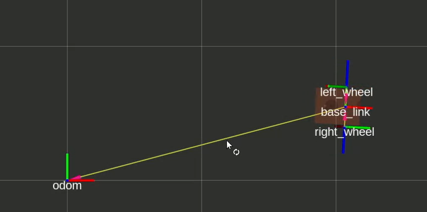
Now here’s the important bit: the motion of base_link relative to odom may not be correct, but it will be smooth. What I mean is, it’s possible that you drive the robot forward in real life by 2m, but when you check RViz, base_link is only 1.9m ahead of odom. This 100mm error did not suddenly appear, it built up over time as the odometry drifted. You could take any small section of that trajectory and it would be nice and smooth and basically correct, but it slowly got away from the truth. This is all because odometry is effectively a measurement of the robot’s velocity, even if it is technically measuring wheel angular position. This velocity is then integrated smoothly over time to produce the transform estimate.
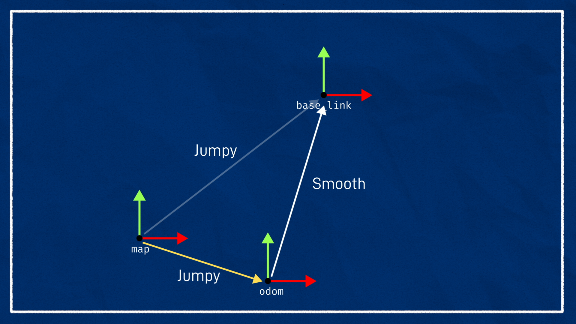
Let’s say we now introduce a system that can correct this drift, like GPS or SLAM. Because these systems directly measure the robot position, if we use them to update the odom-> base_link transform, this could cause the robot to jump around. In many cases this is not a problem, but some algorithms may not like it.
Instead we want to introduce a new "world" frame, the map frame, and we would like to express the location of base_link relative to that, i.e. map -> base_link. There's one issue with this though, which is that a frame can only have one parent. The way we get around this, is that the code will need to take the position estimate from SLAM or GPS or whatever, along with the current odom -> base_link transform, and calculate the appropriate map -> odom transform. This is a bit weird, since the map -> odom transform is kind of meaningless out of context, but it means that we can get the base_link pose relative to either reference point with no troubles. And it should move smoothly, but drift, compared to odom, and jump around but stay generally correct over time, compared to map.
The last thing to be aware of here, is that in addition to base_link some SLAM systems also like to use another frame called base_footprint. This is because in some robots, base_link will move up and down in 3D, but we want to treat this as a 2D SLAM problem. We introduce base_footprint which is the same as base_link except it is bound to the floor, at Z = 0.
One other note on phrasing, I’ll sometimes use the word pose, which refers to the location and orientation of an object in space and is basically equivalent to its transform.
All this coordinate frame stuff can be super confusing but hopefully once we do it in practice it will start to make sense. Also, all the stuff I just said and more can be found in the official ROS standards, REP 105 and 120.
As well as the odom and map frames, you’ll also find odom and map topics which contain the data about the odometry and the map.
The odom topic contains basically the same position information as the odom -> base_link transform, but it also contains the current velocity, and also the associated covariances.
The map topic contains the actual occupancy data for the grid map so that it can be shared to other nodes.
We can use the odometry topic to monitor a robot’s path, and the map topic to view the created map.
Running slam_toolbox
Prep
For this tutorial, we’ll be using the fantastic slam_toolbox package by Steve Macenski. Steve has contributed some amazing packages to the ROS ecosystem, including both slam_toolbox, and Nav2 which we’ll be using in the next video.
We can start by installing slam_toolbox with:
sudo apt install ros-jazzy-slam-toolbox
The other thing we will do to prepare is to add a new link to our robot, the base_footprint mentioned earlier. It’s not really necessary for our robot since it is bound to the ground anyway, but by adding it we reduce the need to change parameters for algorithms that are expecting it to exist.
1
Mapping Mode
Slam_toolbox has a bunch of different modes and options, but everything we’re doing today is what’s called online asynchronous operation. That means we are running live (rather than processing some logged data) and we don’t care about processing every scan, rather if our processing is slower than the scan rate, we just always process the latest scan even if that means we missed some.
Slam_toolbox comes with some launch and params files to help us with this. We’re going to start by copying the online async params file to our own directory so we can modify it.
cp /opt/ros/jazzy/share/slam_toolbox/config/mapper_params_online_async.yaml src/my_bot/config/
Go ahead and open up that file and we’ll be confronted with a huge list of parameters. Don’t worry, we’ll only change a couple of them today, but it’s worth playing around with some of them to see the effects.
The things to be aware of now though are:
- We have our
odom,map, andbase_footprintframes specified (you could usebase_linkhere and skip the previous change). - Our laser data will come from the
/scantopic - We’ll be running in
mappingmode. This is where we are doing SLAM and is in contrast tolocalizationmode, where we don’t care about creating the map, just using it.
1
So in one tab, we’ll start up Gazebo just like normal, driving it around with our gamepad. And we’ll also start up RViz.
If we drive the robot around for a bit and return to the origin (in Gazebo), we can see our odometry drift! It is only subtle in the screenshot below, but the robot is clearly no longer on the origin in RViz and is pointing off to the left. In many situations the odometry drift will be much more pronounced.
To more easily replicate the odometry drift, try increasing the wheel_separation in your diff drive controller to be 10mm larger and then drive around in a full 360° loop (don't just turn one way and then back or it will "undo"). Don't forget to set it back once you've finished experimenting!
After restarting Gazebo to reset the simulation, we can open a new tab and launch slam_toolbox using our config file. We’ll use the provided online_async_launch.py launch file which exposes arguments for the params file path, and also to enable sim time.
ros2 launch slam_toolbox online_async_launch.py use_sim_time:=true params_file:=./src/articubot_one/config/mapper_params_online_async.yaml
Back in RViz, we’ll go ahead and add a Map display and set the topic to /map, and we’re also going to set the fixed frame to map, to keep the map origin stable from our point of view. This means the robot could appear to jump around - if we left odom as the fixed frame then the map may appear to jump instead, it’s just a different view.
As I drive around, you’ll see it start to add new scans in to the map - there are parameters that let you control how it goes about that.
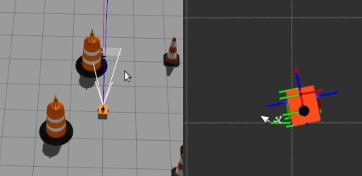
I’ll just swap the camera view to top-down-ortho so that there’s no perspective error, and if l do a big loop around, you’ll see that as I approach my starting position again there are two coordinate frames. If we show names, you can see one is the map, and the other is odom, so this is showing me how much the odom origin has drifted compared to the map origin. And as I get back to where I started, hopefully our map can tell us exactly where we are!
If you changed your wheel separation for this test, make sure you change it back now!
Saving Maps
Once we’ve made our map, we might want to save it to use in the future. Running ros2 service list showes that slam_toolbox offers a range of services for saving and serialising maps, but to make things easier it also comes with an RViz plugin that calls these. So we’ll go to Panels→Add New Panel→SlamToolboxPlugin.
There are a bunch of buttons here but the two we are interested in are “Save Map” and “Serialise Map”. These are a little confusing, but “Save Map” is for saving the map out into a format that other systems can use, while “Serialise Map” is to save it out for slam_toolbox to use again. Type the name you want to use for the file, click the button, and it will be saved in the directory you launched RViz from.
Then if we look at the file listing, we can see there is my_map_save.pgm and .yaml, and we have my_map_serial.data and .posegraph.
Localisation with slam_toolbox
Now that we’ve saved a map, we can try using it in localisation mode. If you want to be sure the next steps work, you may want to first restart slam_toolbox to clear the current map.
Back in our params file, we want to change the mode from mapping to localization.
We also want to uncomment map_file_name and map_start_at_dock. We can set the file name to the absolute path to our serialised map name, without any extension.
Setting it to start at the dock technically means we are starting at the “first node of the graph” which should basically be start at the same place we started last time. We also have the option of manually specifying an initial pose.
If we rerun it now, we should see that our old map pops back up and we can continue from where we left off. One thing you might notice is that it seems to be still generating maps! At first I thought this was just a consequence of how the underlying pose graph works, but after playing around a bit I’m not so sure. Whatever it’s doing, it works very similarly to mapping mode, but the point is we can keep track of our robot.